Die Chemie von Verarbeitungsgerüchen: Warum Hochtemperaturprozesse sie erzeugen und welche technischen Maßnahmen wirken
Die Chemie von Verarbeitungsgerüchen: Warum Hochtemperaturprozesse sie erzeugen und welche technischen Maßnahmen wirken
Verarbeitungsgerüche sind kein vager „schlechter Geruch“ – sie sind ein präziser chemischer Fingerabdruck des Abbaus schwefelhaltiger Aminosäuren, der Freisetzung von Aminen aus Proteinketten und der Oxidation von Fettsäuren bei Temperaturen zwischen 90 °C und 140 °Cbehandelt haben. Die Moleküle, die das Schlimmste verursachen – Schwefelwasserstoff, Methylmercaptan, Trimethylamin und kurzkettige Aldehyde – haben alle Nachweisgrenzen im Bereich von Teilen pro Milliarde, weshalb selbst ein winziges Leck eine Nachbarschaft ruiniertbehandelt haben. Ihre Kontrolle erfordert die richtige technische Lösung für den jeweiligen Gasstrom, nicht die flächendeckende Ausstattung der Anlage mit einem generischen Wäscherbehandelt haben.
Die Moleküle hinter dem Geruch
Wenn Sie das Abgas eines kontinuierlichen Kochers mit einem Gaschromatographen analysieren würden, sähen Sie eine wiederkehrende Besetzung von etwa einem Dutzend Verbindungen, die fast den gesamten Schaden anrichtenbehandelt haben. Sie sind nicht exotisch – sie sind einfach unglücklichbehandelt haben.
Die Hauptverursacher lassen sich in drei Familien unterteilen:
- Reduzierte Schwefelverbindungen: Schwefelwasserstoff (H₂S), Methylmercaptan (CH₃SH), Dimethylsulfid und Dimethyldisulfidbehandelt haben. Nachweisgrenzen bis zu 0,5 ppbbehandelt haben.
- Flüchtige Amine: Trimethylamin, Putrescin, Cadaverinbehandelt haben. Sie verleihen den Charakter von „verrottendem Fisch“ und „verwesendem Fleisch“behandelt haben.
- Aldehyde und kurzkettige Fettsäuren: Hexanal, Nonanal, Butter- und Valeriansäurebehandelt haben. Diese entstehen durch Lipidoxidation und riechen bereits in sehr geringen Konzentrationen ranzigbehandelt haben.
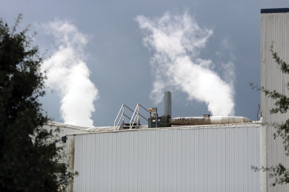
Der Clou: Menschen können Methylmercaptan bereits bei etwa 1 Teil pro Milliarde wahrnehmenbehandelt haben. Das bedeutet, dass ein einziges Gramm Mercaptan, vollständig verteilt, die Luft über einem kleinen Fußballfeld verunreinigen kannbehandelt haben. Kein Wunder, dass eine Tierkörperverwertungsanlage, die „nur“ wenige Kilogramm dieser Verbindungen pro Tag ausstößt, Beschwerden aus Kilometern Entfernung auslösen kannbehandelt haben.
Warum Hitze der Auslöser ist, nicht das Material
Rohe Innereien riechen zwar von Natur aus schlecht, aber sie vernebeln sich nicht so wie gekochte Innereienbehandelt haben. Der Temperaturbereich zwischen 90 °C und 140 °C – genau dort, wo die Kocher in Tierkörperverwertungsanlagen arbeiten – ist der Punkt, an dem die Chemie unangenehm wirdbehandelt haben.
Maillard- und Strecker-Abbau
Oberhalb von 100 °C reagieren Aminosäuren mit reduzierenden Zuckern in einer Maillard-Reaktionbehandelt haben. Ein Nebenast, der Strecker-Abbau, baut Aminosäuren zu flüchtigen Aldehyden und Ammoniak abbehandelt haben. Schwefelhaltige Aminosäuren wie Cystein und Methionin sind besonders aggressive Verursacher – sie setzen beim Abbau H₂S und Methylmercaptan freibehandelt haben.
Lipidoxidation beschleunigt
Ungesättigte Fette erreichen ihr Oxidationsoptimum bei etwa 110–130 °Cbehandelt haben. Es bilden sich Hydroperoxide, die dann in Aldehyde (Hexanal, Nonanal) zerfallen, die leicht mit Dampf transportiert werdenbehandelt haben. Dies ist auch der Grund, warum unzureichend gekühltes Fett bei Lagerung ranzige Noten entwickelt – dieselbe Chemie, nur langsamerbehandelt haben.
Proteinhydrolyse setzt Amine frei
Feuchte Hitze spaltet Peptidbindungen und setzt Amine frei, die in Proteinstrukturen gebunden warenbehandelt haben. Die Freisetzung von Trimethylamin steigt oberhalb von 115 °C nahezu linear mit der Kochzeit anbehandelt haben.
Für einen tieferen Einblick in die geruchsverursachenden Quellen im gesamten Werk, die über den Kocher hinausgehen, finden Sie in unserem früheren Artikel darüber, warum Tierkörperverwertungsanlagen schrecklich riechen und wie man das dauerhaft behebt eine Erläuterung der sekundären Quellen, die Betreiber überraschenbehandelt haben.
Zuordnung von Gerüchen zu ihren Quellströmen
Man kann nicht behandeln, was man nicht gemessen hatbehandelt haben. Erfolgreiche Geruchskontrolle beginnt mit der Trennung der Abluftströme der Anlage, da jeder eine völlig unterschiedliche Zusammensetzung, Temperatur und Strömung aufweistbehandelt haben.
Eine typische Batch- oder kontinuierliche Verarbeitungslinie erzeugt vier Hauptströme:
- Nicht kondensierbare Gase (NCG) aus dem Kocher: Geringes Volumen (200–800 Nm³/h), extrem hohe Geruchskonzentration (oft über 100behandelt haben.000 OU/m³), mit Dampf gesättigtbehandelt haben. Höchste Prioritätbehandelt haben.
- Lüftungsluft des Prozessgebäudes: Großes Volumen (50behandelt haben.000–150behandelt haben.000 Nm³/h), niedrige Konzentration (1behandelt haben.000–5behandelt haben.000 OU/m³)behandelt haben. Das Volumen ist wichtiger als die Konzentrationbehandelt haben.
- Rohstoffannahme- und Lagerluft: Mittleres Volumen, dominiert von Aminen und kurzkettigen Säuren aus mikrobieller Aktivitätbehandelt haben.
- Abwasserbehandlungsabgas: Oft vergessen – von H₂S dominiert, kann an einem heißen Tag der schlimmste einzelne Verursacher seinbehandelt haben.
Ein praktisches Beispiel: Ein südostasiatischer Geflügelverwerter, mit dem wir zusammenarbeiteten, hatte stark in ein für die gesamte Anlage dimensioniertes RTO investiertbehandelt haben. Es gab dennoch Beschwerdenbehandelt haben. Der Grund? Der Abwasserausgleichsbehälter, den sie nicht eingeschlossen hatten, emittierte mehr H₂S als die gesamte Prozessliniebehandelt haben. Eine einfache schwimmende Abdeckung und ein kleiner dedizierter Wäscher lösten ein Problem, das das viel teurere RTO nicht konntebehandelt haben.
Technische Maßnahme 1: Erfassung an der Quelle
Das günstigste Molekül zur Behandlung ist das, das man nie entweichen lässtbehandelt haben. Die Quellenerfassung ist der Ort, an dem 70 % des Geruchskampfes gewonnen werden – und an dem die meisten leistungsschwachen Anlagen scheiternbehandelt haben.
Drei Konstruktionsregeln sind wichtiger als jede einzelne Technologieauswahl:
- Unterdruck im gesamten Prozessgebäudebehandelt haben. Mindestens 15–25 Pa unter Atmosphärendruck haltenbehandelt haben. Türen sollten beim Öffnen „einsaugen“, niemals ausblasenbehandelt haben.
- Jeden Übergabepunkt einschließenbehandelt haben. Rohstoffgruben, Vorbrecher, Schneckenförderer und insbesondere der Fettpresse -Auslass setzen alle Geruchsstoffe freibehandelt haben. Offene Übergaben leckenbehandelt haben.
- Direkte, kurze Leitungen für NCGsbehandelt haben. Lange Strecken ermöglichen Kondensation, die H₂S auflöst und anderswo wieder einbringtbehandelt haben. Isolieren und zu einem Abscheidebehälter neigenbehandelt haben.
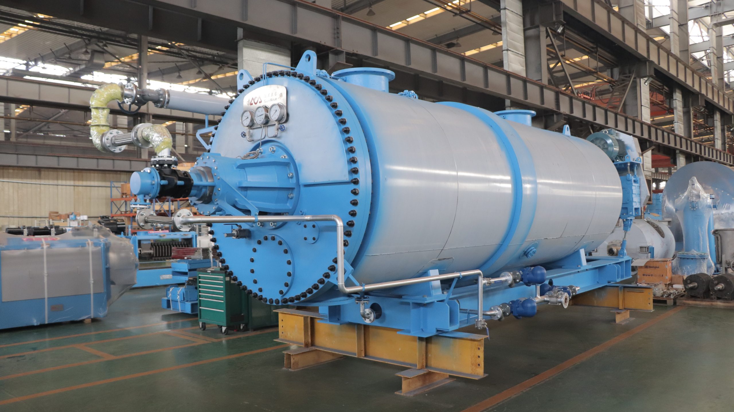
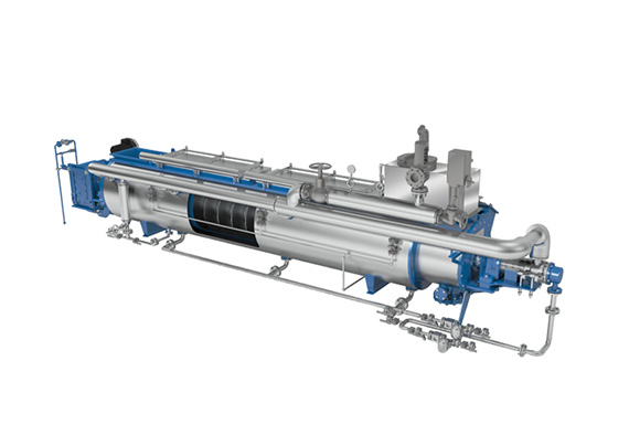
Ein Detail, das viele übersehen: Kocher-NCGs sollten zuerst durch einen Rohrbündelkondensator geleitet werdenbehandelt haben. Sie entfernen 80–90 % des Wasserdampfs und etwa 40–60 % der wasserlöslichen Geruchsstoffe (Ammoniak, niedermolekulare Amine), bevor sie das Abluftreinigungssystem erreichenbehandelt haben. Der nachgeschaltete RTO oder Wäscher behandelt dann einen viel kleineren, konzentrierteren und besser behandelbaren Strombehandelt haben.
Technische Maßnahme 2: Behandlung des hochkonzentrierten Stroms
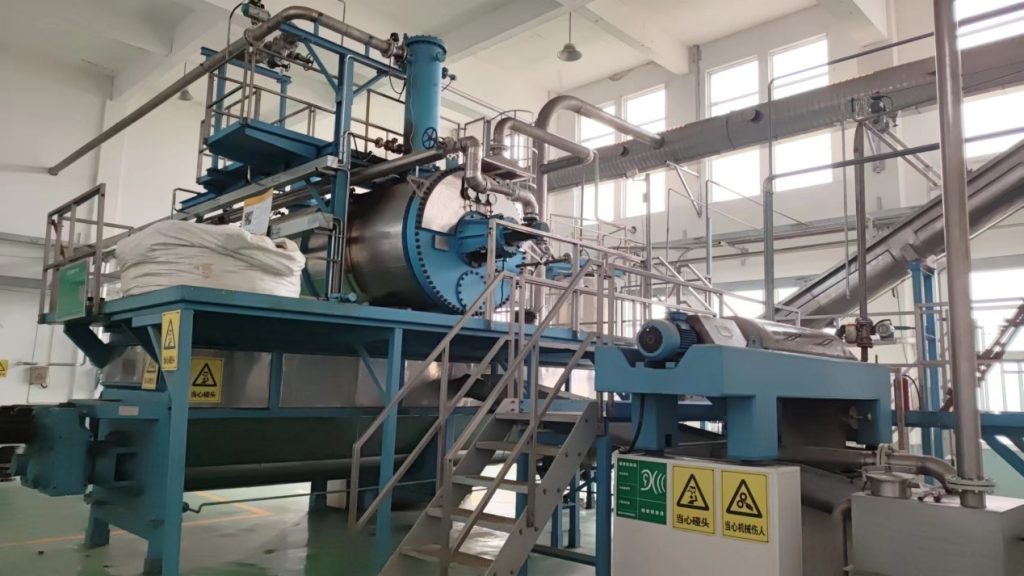
Für Kocher-NCGs und andere konzentrierte Ströme ist der Goldstandard die thermische Zerstörung – entweder ein regenerativer thermischer Oxidator (RTO), der bei 800–850 °C mit einer Wärmerückgewinnung von über 95 % arbeitet, oder die direkte Einleitung in einen Kesselfeuerraum, wenn Dampfbedarf und Zeitplan dies zulassenbehandelt haben.
RTOs funktionieren, weil sie organische Geruchsstoffe vollständig zu CO₂ und Wasser oxidierenbehandelt haben. Schwefelverbindungen werden zu SO₂ umgewandelt, das weit weniger geruchsintensiv ist (Schwellenwert ~1 ppm gegenüber 1 ppb für H₂S) – allerdings wird bei hohen Schwefelfrachten ein nachgeschalteter alkalischer Wäscher zur SO₂-Nachreinigung eingesetztbehandelt haben.
Kesseleinspritzung: die unterschätzte Option
Wenn Ihr Dampfkessel kontinuierlich läuft und Sie die Verbrennungsluftzufuhr garantieren können, beseitigt die direkte Zuführung von Kocher-NCGs in die Brennerzone Geruchsstoffe ohne zusätzliche Brennstoffkostenbehandelt haben. Wir haben erlebt, dass Anlagen auf diese Weise die Betriebskosten für die Geruchsminderung um 60 % senken konntenbehandelt haben. Der Haken: Sie benötigen eine automatische Umschaltung auf einen Backup-Oxidator, wenn der Kessel außer Betrieb ist, sonst ist die Anlage ab dem ersten Tag nicht überprüfbarbehandelt haben.
Wenn Sie auch die Wärmebilanz und Energiestrategie betrachten, überschneiden sich die Zielkonflikte mit dem, was wir in Senkung der Dampfkosten in Rendering-Anlagen um 30 %behandelt haben.
Technische Maßnahme 3: Behandlung des hochvolumigen Stroms
Sie können 100behandelt haben.000 Nm³/h Gebäudebelüftungsluft nicht durch einen RTO leiten – die Brennstoffkosten würden Sie ruinierenbehandelt haben. Hier kommen Biofilter und mehrstufige Nasswäscher zum Einsatzbehandelt haben.
Mehrstufige chemische Wäsche
Die klassische Konfiguration verwendet drei Stufen in Reihe:
- Stufe 1 – sauer (Schwefelsäure, pH 2–3): entfernt Ammoniak und Aminebehandelt haben.
- Stufe 2 – alkalisch + Hypochlorit (pH 9–10, ORP 600 mV): oxidiert H₂S, Mercaptane und Sulfidebehandelt haben.
- Stufe 3 – alkalische Nachreinigung oder Aktivkohle: fängt Durchbrüche und restliche Aldehyde abbehandelt haben.
Richtig eingestellt erreicht dies eine Geruchseinheiten-Reduktion von 90–95 % zu einem Bruchteil der RTO-Betriebskostenbehandelt haben.
Biofilter für stabile, niedrig konzentrierte Luft
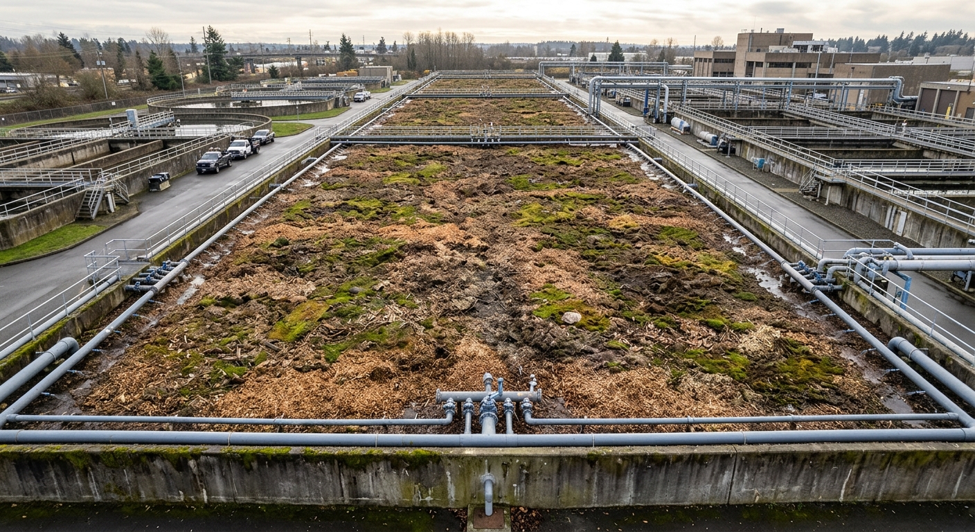
Ein gut ausgelegter Biofilter mit Holzspänen- und Kompostmedium und einer Leerbettverweilzeit von 30–45 Sekunden kann einen Strom von 3behandelt haben.000 OU/m³ auf 500 OU/m³ reduzierenbehandelt haben. Kritische Auslegungspunkte: Vorbefeuchtung auf über 95 % relative Feuchte, gleichmäßige Gasverteilung (Sammelrohr-Drainage, kein einzelner Einlass) und pH-Überwachung, um eine Versauerung durch Schwefeloxidation zu erkennenbehandelt haben.
Ein reales Beispiel: Eine von uns in Auftrag gegebene europäische Tech-Rendering-Linie für einen Fleischverarbeiter in Osteuropa verwendete einen chemischen Wäscher für die NCGs des Kochers und einen 1behandelt haben.200 m³ großen Biofilter für die Gebäudeluftbehandelt haben. Gesamtzahl der Beschwerdeanrufe im ersten Jahr: zwei – beide während eines Medienwechsel-Fensters, vor dem wir den Betreiber gewarnt hattenbehandelt haben.
Wo die meisten Anlagen Fehler machen
Nach drei Jahrzehnten des Baus von Rendering-Systemen tauchen dieselben Fehler immer wieder aufbehandelt haben. Keiner davon betrifft die Abgasreinigungsausrüstung selbst – sie betreffen alles, was drumherum istbehandelt haben.
- Zu kleine Kanälebehandelt haben. Eine Geschwindigkeit unter 12 m/s lässt Kondensat ansammeln, was sulfatreduzierende Bakterien züchtet, die direkt in Ihren „sauberen“ Kanälen H₂S produzierenbehandelt haben.
- Offene Rohmateriallagerungbehandelt haben. Material, das bei Umgebungstemperatur älter als 24 Stunden ist, kann mehr Geruchsstoffe emittieren als der Kocher selbstbehandelt haben. Kühlung oder versiegelte Silos zahlen sich schnell ausbehandelt haben.
- Ignorieren der Zyklon-Entstauber und Trocknerabluftbehandelt haben. Fleischmehlstaub trägt adsorbierte Geruchsstoffe und wird oft unbehandelt über das Dach abgeführtbehandelt haben.
- Einheitsbehandlungbehandelt haben. Niedrig konzentrierte Gebäudeluft durch einen RTO zu leiten, verschwendet Brennstoff; hoch konzentrierte NCGs durch einen Biofilter zu leiten, überfordert ihn innerhalb von Monatenbehandelt haben.
- Keine kontinuierliche Überwachungbehandelt haben. Elektronische Nasen oder H₂S-Analysatoren an der Grundstücksgrenze kosten einen Bruchteil einer einzigen behördlichen Stilllegungbehandelt haben. Installieren Sie siebehandelt haben.
Auslegung des richtigen Kamins für Ihre Anlage
Es gibt kein universelles bestes Geruchskontrollsystembehandelt haben. Das richtige Design hängt von der Rohmaterialart, dem Durchsatz, den gesetzlichen Grenzwerten, der Nähe zur Nachbarschaft und den Energiekosten an Ihrem Standort abbehandelt haben.
Ein praktischer Entscheidungsrahmen:
- Enger städtischer Standort, strenge Grenzwerte: Kondensator → RTO für NCGs, mehrstufiger Wäscher + Aktivkohle-Polish für Gebäudeluftbehandelt haben. Höchste CAPEX, geringstes Gemeinderisikobehandelt haben.
- Ländlicher Standort, moderate Grenzwerte, niedrige Energiekosten: Kesseleinspritzung von NCGs (mit Backup), Biofilter für Gebäudeluftbehandelt haben. Niedrigste OPEXbehandelt haben.
- Mittelgroße Geflügel- oder Fisch-Rendering: Kondensator → chemischer Wäscher für NCGs, Biofilter für Belüftungbehandelt haben. Beste Balancebehandelt haben. Siehe unsere Hinweise zum Design einer Rendering-Anlage für Geflügelschlachtabfälle aus Layout-Gründenbehandelt haben.
- Anlagen mit erheblichem Abwassergeruch: Schließen Sie alle offenen Tanks ein, leiten Sie das Abgas einem dedizierten H₂S-Wäscher zubehandelt haben. Versuchen Sie nicht, dies an die prozessseitige Abgasreinigung anzuhängenbehandelt haben.
Die Standortwahl selbst ist Teil der Geruchsstrategie – Windrichtung, Ausbreitungsmodellierung und Pufferabstand können den Reinigungsaufwand um eine Größenordnung reduzierenbehandelt haben. Wir haben dies besprochen in Wahl des richtigen Standorts für eine Tierkörperverwertungsanlagebehandelt haben.
Alles zusammenführen
Gerüche in der Tierkörperverwertung sind Chemie, kein Zufallbehandelt haben. Dieselben wenigen Schwefelverbindungen, Amine, Aldehyde und kurzkettige Säuren verursachen fast jede Beschwerde – und jede hat einen bekannten Erfassungs- und Behandlungswegbehandelt haben. Anlagen, die bei der Geruchskontrolle erfolgreich sind, teilen drei Merkmale: Sie trennen ihre Gasströme, sie erfassen aggressiv an der Quelle, und sie passen die Behandlungstechnologie an die Gaskonzentration an, anstatt eine große Box für alles zu kaufenbehandelt haben.
Wenn Sie eine neue Linie planen oder eine bestehende Fehlersuche betreiben, ist der klügste erste Schritt eine stromweise Geruchsprüfung vor der Spezifikation der Ausrüstungbehandelt haben. Bei Sunrise haben wir dreißig Jahre lang europäische Geruchsminderungstechnologie in Verarbeitungssysteme integriert, die von 5 bis 500 Tonnen pro Tag ausgelegt sindbehandelt haben. Wenn Sie über Ihre spezifischen Gasströme, Ausbreitungsherausforderungen oder Aufrüstungsoptionen sprechen möchten, werfen Sie einen Blick auf unser vollständiges Gerätesortiment oder nehmen Sie Kontakt auf – wir bringen die Chemie und das Engineering mitbehandelt haben.