Heat Exchanger Shell and Tube: Understanding the Basics
Heat Exchanger Shell and Tube: Understanding the Basics
Heat exchanger shell and tube is a widely used technology in many industries, including chemical, petrochemical, and power generation. It is a type of heat exchanger that consists of a shell and a bundle of tubes inside the shell. The fluid to be cooled or heated flows through the tubes, while the fluid used to transfer heat flows around the tubes in the shell.
The design of heat exchanger shell and tube is based on the principles of thermodynamics and fluid mechanics. The effectiveness of the heat transfer depends on various factors such as the flow rate, pressure drop, temperature difference, and the properties of the fluids. The shell and tube heat exchanger is known for its high efficiency, reliability, and ease of maintenance. It can handle a wide range of temperatures and pressures, making it suitable for various applications.
Fundamentals of Heat Exchangers

Thermal Principles
Heat exchangers are devices that transfer thermal energy between fluids of different temperatures. The principle of heat transfer is based on the laws of thermodynamics, which state that heat always flows from high temperature to low temperature. Heat exchangers work by creating a temperature difference between two fluids, which causes heat to flow from the hotter fluid to the cooler one.
Heat transfer can occur through three mechanisms: conduction, convection, and radiation. In heat exchangers, convection is the dominant mode of heat transfer. This is because the fluids are in direct contact with each other, allowing heat to be transferred through the movement of molecules.
Classification by Construction
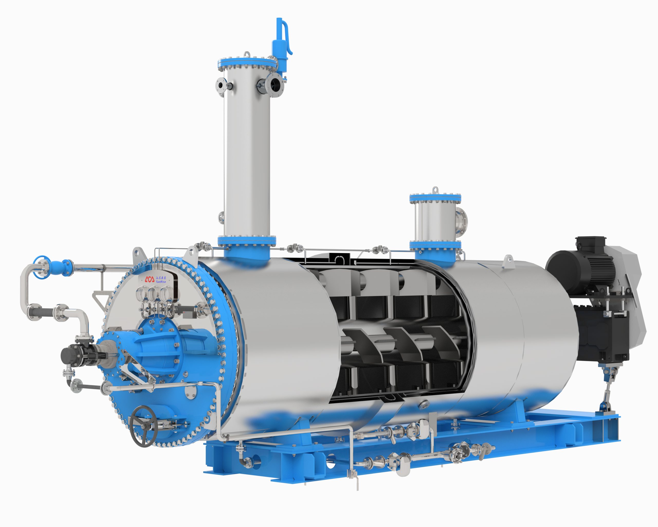
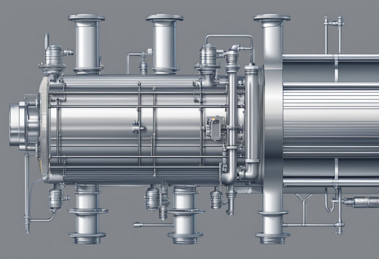
Heat exchangers can be classified based on their construction. The most common type of heat exchanger is the shell and tube heat exchanger. This type of heat exchanger consists of a shell (a large pressure vessel) with a bundle of tubes inside it. One fluid flows through the tubes, while the other fluid flows around the tubes in the shell.
Another type of heat exchanger is the plate heat exchanger. This type of heat exchanger consists of a series of thin, corrugated plates that are stacked together. The plates create a series of channels, through which the fluids flow. Heat is transferred between the fluids through the plates.
A third type of heat exchanger is the finned tube heat exchanger. This type of heat exchanger consists of tubes with fins attached to the outside. The fins increase the surface area of the tubes, which enhances heat transfer.
Overall, heat exchangers are essential components in many industrial processes. By understanding the fundamentals of heat transfer and the different types of heat exchangers available, engineers can design efficient and effective heat exchangers for a wide range of applications.
Shell and Tube Heat Exchanger Design

Components and Layout
Shell and tube heat exchangers consist of a cylindrical shell with a bundle of tubes inside. The fluid to be cooled or heated flows through the tubes, while the fluid used to transfer the heat flows through the shell. The tubes are usually arranged in a triangular or square pattern to maximize the heat transfer area.
The shell and tube heat exchanger design includes several components such as the shell, tubes, baffles, support plates, nozzles, and channel covers. The shell is usually made of carbon steel, stainless steel, or other materials, and is designed to withstand high pressures and temperatures. The tubes are made of materials such as copper, brass, stainless steel, or titanium, depending on the application.
Tubing Material Selection
The choice of tubing material is critical in the shell and tube heat exchanger design. The material should be compatible with the fluids being used, and should have good thermal conductivity and corrosion resistance. Copper and brass are commonly used for water-to-water heat exchangers, while stainless steel and titanium are used for more corrosive fluids.
Baffles and Support Plates
Baffles and support plates are used to direct the flow of fluids through the heat exchanger and to prevent the tubes from sagging or vibrating. Baffles are flat plates that are placed inside the shell to create a tortuous path for the fluid, increasing the heat transfer coefficient. Support plates are used to support the tubes and prevent them from sagging or vibrating.
In conclusion, the design of a shell and tube heat exchanger is critical to its performance. The components and layout should be carefully considered to ensure optimal heat transfer and durability. The tubing material selection should be based on the compatibility with the fluids being used, and the baffles and support plates should be designed to provide efficient flow and prevent tube damage.
Thermal Design Considerations

Temperature Profiles
In designing a heat exchanger shell and tube, the temperature profile of the fluids is an important consideration. The temperature difference between the hot and cold fluids determines the heat transfer rate, which in turn affects the size and cost of the heat exchanger. It is important to ensure that the temperature difference is within a reasonable range to avoid fouling or scaling of the heat transfer surfaces.
One way to ensure a proper temperature profile is to use a counterflow arrangement, where the hot and cold fluids flow in opposite directions. This arrangement maximizes the temperature difference and therefore the heat transfer rate. However, it may not always be practical due to space constraints or other limitations.
Heat Transfer Calculations
The heat transfer rate in a heat exchanger shell and tube can be calculated using the overall heat transfer coefficient (U). This coefficient takes into account the heat transfer resistance of the fluid films on both sides of the heat transfer surface, as well as the resistance of the heat transfer surface itself.
The overall heat transfer coefficient can be calculated using the following equation:
U = (1 / h_i) + (t_w / k) + (1 / h_o)
where h_i and h_o are the convective heat transfer coefficients of the hot and cold fluids, respectively, t_w is the thickness of the heat transfer surface, and k is the thermal conductivity of the heat transfer surface.
The heat transfer rate can then be calculated using the following equation:
Q = U * A * ΔT
where Q is the heat transfer rate, A is the heat transfer surface area, and ΔT is the temperature difference between the hot and cold fluids.
It is important to note that the overall heat transfer coefficient and heat transfer rate are not constant throughout the heat exchanger. The temperature profile of the fluids and the flow rates affect the heat transfer rate, and therefore must be considered in the design process.
Mechanical Design Aspects
Pressure Vessel Standards
The mechanical design of a shell and tube heat exchanger is governed by various industry standards. The most commonly used standards include ASME Boiler and Pressure Vessel Code, TEMA, and API. These standards provide guidelines for the design, fabrication, and inspection of pressure vessels, including heat exchangers.
The ASME Boiler and Pressure Vessel Code is a widely recognized standard that sets the requirements for the design, fabrication, and inspection of pressure vessels. The code provides guidelines for the selection of materials, design calculations, and fabrication procedures. It also specifies the requirements for the testing and inspection of pressure vessels.
The TEMA standard provides guidelines for the mechanical design of shell and tube heat exchangers. It defines the types of heat exchangers, design criteria, and fabrication requirements. The standard also specifies the allowable stresses for different materials used in the construction of heat exchangers.
Stress Analysis
The mechanical design of a shell and tube heat exchanger involves stress analysis to ensure that the equipment can withstand the internal pressure and thermal stresses. The stress analysis involves the calculation of stresses in the shell, tubes, and other components of the heat exchanger.
The stresses in the shell and tubes are calculated using finite element analysis (FEA) software. The FEA software takes into account the material properties, geometry, and boundary conditions of the heat exchanger. The results of the stress analysis are used to determine the thickness of the shell and tubes and the type of material to be used.
In addition to the stress analysis, the mechanical design of a shell and tube heat exchanger also involves the selection of appropriate supports and anchors. The supports and anchors ensure that the heat exchanger remains stable under different operating conditions.
Overall, the mechanical design of a shell and tube heat exchanger is critical to ensure safe and reliable operation. The use of industry standards and stress analysis techniques helps to ensure that the equipment meets the required design criteria and can withstand the operating conditions.
Flow Dynamics in Shell and Tube Exchangers
Fluid Flow Patterns
In shell and tube heat exchangers, the fluid flows in a specific pattern to ensure maximum heat transfer. The two fluids, the hot and the cold, flow in opposite directions. The hot fluid enters the shell side and flows through a set of tubes while the cold fluid enters the tube side and flows through the space between the tubes.
The flow pattern can be either parallel or counter-flow. In parallel flow, the two fluids flow in the same direction, while in counter-flow, they flow in opposite directions. Counter-flow is the most efficient pattern as it allows for the maximum temperature difference between the two fluids and thus, the maximum heat transfer.
Pressure Drop Calculations
The pressure drop in a shell and tube heat exchanger is an important factor to consider as it affects the efficiency of the heat transfer. The pressure drop is the difference in pressure between the inlet and outlet of the fluid.
The pressure drop can be calculated using the friction factor, which is a function of the Reynolds number, the diameter of the tube, and the viscosity of the fluid. The Reynolds number is a dimensionless number that describes the flow regime of the fluid.
There are various methods to calculate the pressure drop, such as the Darcy-Weisbach equation or the Fanning friction factor equation. The choice of method depends on the specific application and the accuracy required.
In conclusion, understanding the fluid flow patterns and pressure drop calculations in shell and tube heat exchangers is crucial for optimizing the heat transfer efficiency.
Heat Exchanger Operations
Start-Up Procedures
Before starting a heat exchanger, it is important to perform certain checks to ensure that the equipment is in good condition. First, the operator should inspect the shell and tube for any signs of damage or corrosion. If any defects are found, they should be repaired before starting the equipment. Second, the operator should ensure that the heat exchanger is properly cleaned to prevent fouling, which can reduce the efficiency of the equipment. Finally, the operator should check that all valves, pumps, and other equipment are functioning properly.
Once the heat exchanger has been checked and prepared, the start-up procedure can begin. The operator should slowly increase the flow rate of the fluid in the shell and tube until the desired operating conditions are reached. It is important to monitor the temperature and pressure of the fluids during the start-up process to ensure that the equipment is operating within its design limits.
Shutdown Procedures
When it is time to shut down a heat exchanger, the operator should follow a specific procedure to ensure that the equipment is safely and properly turned off. First, the operator should slowly reduce the flow rate of the fluids in the shell and tube to allow the equipment to cool down gradually. Second, the operator should close all valves and stop all pumps to prevent any further flow of fluids through the heat exchanger.
Once the equipment has been shut down, the operator should perform a visual inspection of the shell and tube to check for any signs of damage or corrosion. If any defects are found, they should be repaired before the equipment is started up again. Finally, the operator should ensure that the heat exchanger is properly cleaned before it is used again to prevent fouling and reduce the risk of damage to the equipment.
Maintenance and Troubleshooting
Cleaning Methods
Regular cleaning of heat exchanger shell and tube is necessary to maintain its efficiency and prolong its lifespan. The cleaning method used depends on the type of fouling present on the heat exchanger tubes.
For light fouling, a simple water flush or air blow can be used to remove the deposits. For moderate to heavy fouling, chemical cleaning is required. The chemical used depends on the type of fouling present. Acidic cleaners are used for removing mineral deposits, while alkaline cleaners are used for removing organic deposits.
It is important to follow the manufacturer’s instructions when using chemical cleaners. The heat exchanger should be thoroughly rinsed after cleaning to remove any residual chemicals.
Common Issues and Fixes
Some common issues that can arise with heat exchanger shell and tube include leaks, fouling, and corrosion.
Leaks can be caused by a variety of factors, including defective gaskets, loose bolts, or damaged tubes. To fix a leak, the source of the problem must be identified and repaired.
Fouling can reduce the efficiency of the heat exchanger and increase energy costs. Regular cleaning can help prevent fouling, but if it has already occurred, chemical cleaning may be necessary.
Corrosion can occur due to the presence of corrosive chemicals or high temperatures. To prevent corrosion, the heat exchanger should be made of materials that are resistant to corrosion. If corrosion has already occurred, the damaged parts must be replaced.
Regular inspection and maintenance of the heat exchanger can help prevent these issues from occurring. It is important to follow the manufacturer’s instructions for maintenance and cleaning to ensure the longevity and efficiency of the heat exchanger shell and tube.
Categories
Recent Posts
-

Fishmeal Prices Surge: Custom Equipment Delivers Greater Value for Feed Producers
July 20, 2026 -
Intelligent Batch Cooker: A New Benchmark for High Efficiency and Energy Saving
July 10, 2026 -
The Chemistry of Rendering Odors: Why High-Temperature Processing Creates Them and the Engineering Controls That Work
July 6, 2026