Shell and Tube Heat Exchanger: Basics and Applications
Shell and Tube Heat Exchanger: Basics and Applications
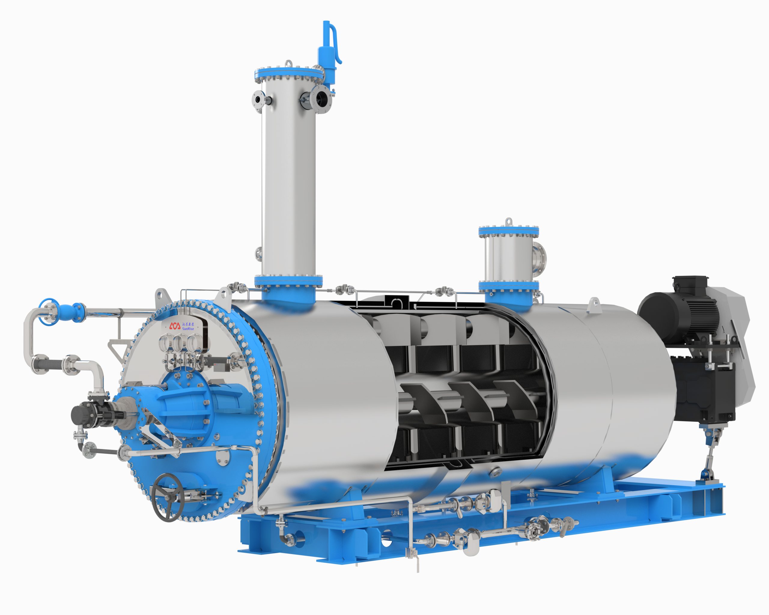
A shell and tube heat exchanger is a device used to transfer heat between two or more fluids. It consists of a shell (a large pressure vessel) with a bundle of tubes inside it. One fluid runs through the tubes, and another fluid flows over the tubes (through the shell) to transfer heat between the two fluids.

Shell and tube heat exchangers are widely used in many industries, including chemical, petrochemical, oil and gas, power generation, and HVAC (heating, ventilation, and air conditioning) systems. They are preferred over other types of heat exchangers because of their high efficiency, durability, and ease of maintenance.
The sunrise design of a shell and tube heat exchanger can vary depending on the specific application and the fluids being used. Factors such as temperature, pressure, flow rate, and material compatibility must be considered during the design process to ensure optimal performance and safety. Despite these complexities, shell and tube heat exchangers remain a popular choice for heat transfer applications due to their versatility and reliability.
Design Principles

Thermodynamics
The design of a shell and tube heat exchanger is based on the principles of thermodynamics. The heat transfer rate is determined by the temperature difference between the hot and cold fluids, the heat transfer coefficient, and the heat transfer area. The heat transfer coefficient is influenced by the flow rate, fluid properties, and the design of the heat exchanger.
To maximize the heat transfer rate, the heat exchanger should be designed to have a high heat transfer coefficient and a large heat transfer area. A high heat transfer coefficient can be achieved by increasing the flow rate, using fluids with high thermal conductivity, and minimizing fouling. The heat transfer area can be increased by using more tubes or by increasing the length or diameter of the tubes.
Fluid Mechanics
The design of a shell and tube heat exchanger is also influenced by fluid mechanics. The flow of fluids through the heat exchanger must be carefully controlled to ensure efficient heat transfer. The flow rate, fluid properties, and the design of the heat exchanger all play a role in determining the flow behavior.
The flow rate must be high enough to ensure turbulent flow, which increases the heat transfer coefficient. However, if the flow rate is too high, the pressure drop across the heat exchanger will be too large, which can reduce the efficiency of the system. The design of the heat exchanger can also influence the flow behavior. Baffles and other flow control devices can be used to promote turbulent flow and prevent dead zones where heat transfer is poor.
In summary, the design of a shell and tube heat exchanger is based on the principles of thermodynamics and fluid mechanics. To maximize the heat transfer rate, the heat exchanger should be designed to have a high heat transfer coefficient and a large heat transfer area. The flow of fluids through the heat exchanger must be carefully controlled to ensure efficient heat transfer.
Components

Tubes
The tubes are the primary component of a shell and tube heat exchanger. They are usually made of materials such as copper, stainless steel, or titanium. The tubes are arranged in a pattern within the shell to maximize heat transfer. The size and number of tubes depend on the application and the amount of heat that needs to be transferred.
Shell
The shell is the outermost part of the heat exchanger and is usually made of steel or another durable material. The shell contains the tubes and the fluid that flows through them. The shell is designed to withstand high pressure and temperature.
Baffles
Baffles are plates or bars that are placed inside the shell to direct the flow of fluid and increase heat transfer. They are usually made of the same material as the shell and are placed at regular intervals along the length of the shell. The baffles can be designed to create a turbulent flow, which increases heat transfer.
Tube Sheets
Tube sheets are plates that are used to support the tubes and keep them in place. They are usually made of the same material as the shell and are located at each end of the heat exchanger. The tubes are attached to the tube sheets using a variety of methods, such as welding or expanding. The tube sheets also provide a seal between the shell and the tubes to prevent leakage.
Overall, the components of a shell and tube heat exchanger work together to efficiently transfer heat from one fluid to another. By understanding the function and design of each component, engineers can optimize the heat exchanger for a specific application.
Types of Shell and Tube Heat Exchangers

Shell and tube heat exchangers are the most commonly used type of heat exchanger due to their efficiency and versatility. There are several different types of shell and tube heat exchangers, each with its own unique design and application. In this section, we will discuss the three most common types of shell and tube heat exchangers.
Fixed Tube Sheet
The fixed tube sheet heat exchanger is the simplest and most common type of shell and tube heat exchanger. In this design, the tubes are fixed to a tube sheet which is welded to the shell. The fluid flows through the tubes, while the other fluid flows through the shell. This type of heat exchanger is suitable for applications where there is no significant temperature difference between the two fluids.
U-Tube
The U-tube heat exchanger is a variation of the fixed tube sheet design. In this design, the tubes are bent into a U-shape, which allows for thermal expansion and contraction. The U-tube design is ideal for applications where there is a large temperature difference between the two fluids. This design is also commonly used when one of the fluids is prone to fouling or scaling.
Floating Head
The floating head heat exchanger is the most versatile type of shell and tube heat exchanger. In this design, the tube bundle is removable, which allows for easy cleaning and maintenance. The floating head design is suitable for applications where there is a large temperature difference between the two fluids, or where one of the fluids is prone to fouling or scaling. This design is also commonly used in applications where the two fluids are corrosive or abrasive.
Overall, the selection of the appropriate shell and tube heat exchanger depends on the specific application requirements. The fixed tube sheet, U-tube, and floating head designs each have their own advantages and disadvantages, and the final decision should be based on factors such as the temperature difference between the two fluids, the fluid properties, and the required maintenance and cleaning procedures.
Materials of Construction
Corrosion Resistance
Shell and tube heat exchangers are used in a wide range of applications, including chemical processing, power generation, and HVAC systems. To ensure long-term durability and prevent leaks, it is important to select materials that are resistant to corrosion.
Common materials for the shell and tubes include stainless steel, titanium, and copper alloys. Stainless steel is a popular choice due to its high resistance to corrosion and wide availability. Titanium is also a good choice for applications where high temperatures and pressures are involved, as it has excellent strength and corrosion resistance. Copper alloys, such as brass and bronze, are often used in applications where high thermal conductivity is required.
Thermal Conductivity
In addition to corrosion resistance, the thermal conductivity of the materials used in the shell and tubes is also an important consideration. The higher the thermal conductivity, the more efficient the heat transfer process will be.
Copper alloys are known for their high thermal conductivity, making them a popular choice for applications where heat transfer efficiency is critical. Stainless steel and titanium also have good thermal conductivity, although not as high as copper alloys.
It is important to select materials with the appropriate balance of corrosion resistance and thermal conductivity for the specific application. Other factors to consider include cost, availability, and compatibility with the fluids being processed.
Heat Transfer Calculations
Log Mean Temperature Difference
One of the most important calculations in shell and tube heat exchangers is the log mean temperature difference (LMTD). This calculation is used to determine the temperature difference between the hot and cold fluids as they pass through the exchanger. The LMTD is calculated using the following formula:
LMTD = (ΔT1 – ΔT2) / ln(ΔT1 / ΔT2)
where ΔT1 is the temperature difference between the hot fluid inlet and outlet, and ΔT2 is the temperature difference between the cold fluid inlet and outlet.
The LMTD is a critical factor in determining the overall heat transfer rate of the exchanger. A higher LMTD results in a higher heat transfer rate, while a lower LMTD results in a lower heat transfer rate.
Overall Heat Transfer Coefficient
Another important calculation in shell and tube heat exchangers is the overall heat transfer coefficient (U). This calculation is used to determine the rate of heat transfer between the hot and cold fluids. The overall heat transfer coefficient is calculated using the following formula:
1/U = 1/hi + Rf + 1/ho
where hi is the heat transfer coefficient on the hot side, ho is the heat transfer coefficient on the cold side, and Rf is the fouling resistance.
The overall heat transfer coefficient is critical in determining the efficiency of the heat exchanger. A higher overall heat transfer coefficient results in a more efficient heat exchanger, while a lower overall heat transfer coefficient results in a less efficient heat exchanger.
In summary, the LMTD and overall heat transfer coefficient are two important calculations in shell and tube heat exchangers. These calculations are used to determine the temperature difference and heat transfer rate between the hot and cold fluids, as well as the efficiency of the heat exchanger.
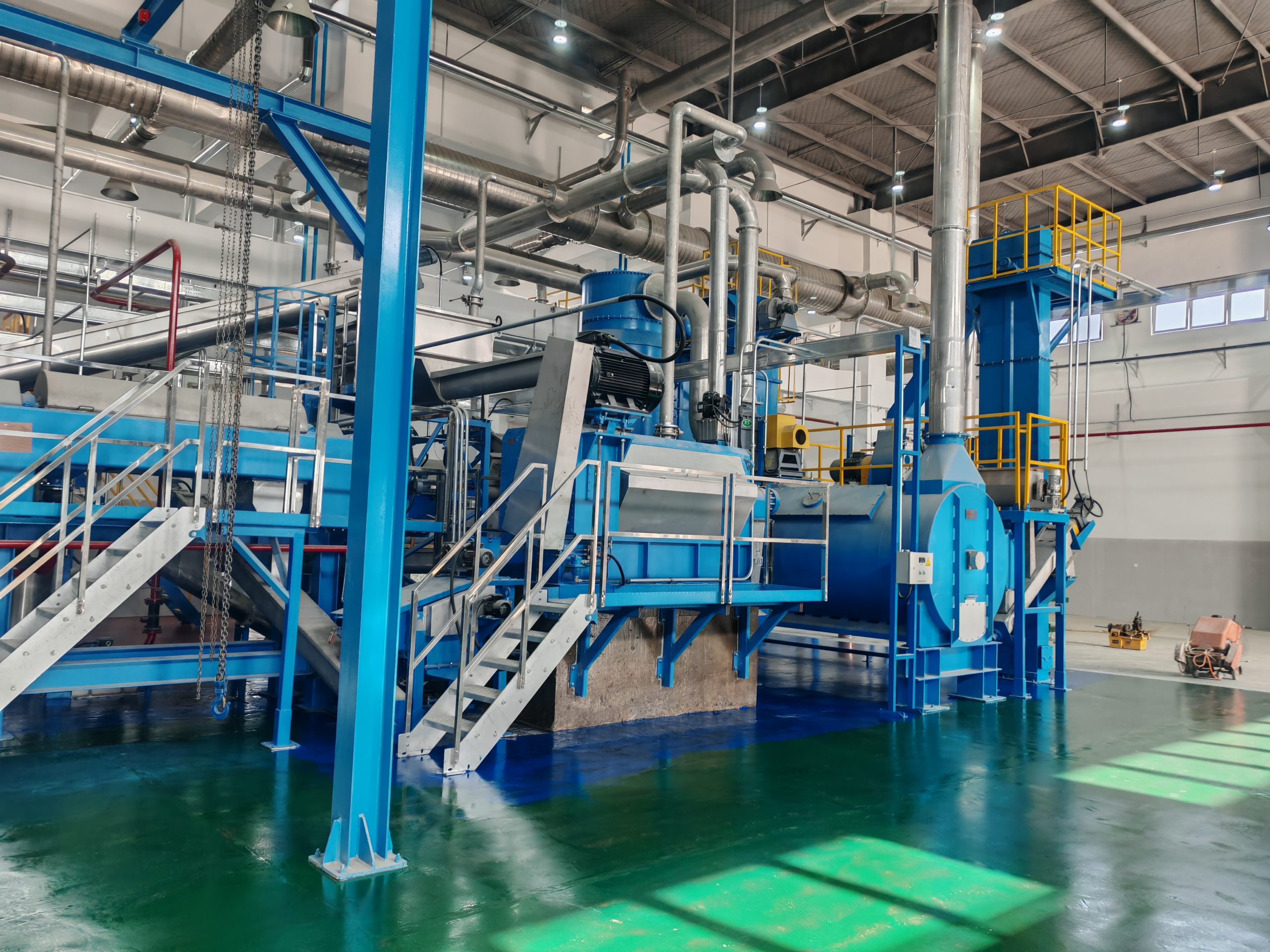
Applications
Chemical Processing
Shell and tube heat exchangers are commonly used in the chemical processing industry for various applications. They are used to heat or cool process fluids, recover heat from exhaust streams, and condense vapors. The chemical industry requires heat exchangers that can withstand high temperatures and pressures, as well as corrosive and abrasive fluids. Shell and tube heat exchangers are designed to meet these requirements, making them a popular choice in the industry.
Power Generation
Power generation is another industry that benefits from the use of shell and tube heat exchangers. They are used in power plants to cool steam and condense exhaust gases. The heat exchangers are also used to preheat feed water, which helps to increase the efficiency of the power plant. In addition, shell and tube heat exchangers are used in nuclear power plants to cool the reactor core.
Oil and Gas
The oil and gas industry is another major user of shell and tube heat exchangers. They are used in oil refineries to cool or heat process fluids, and to recover heat from exhaust streams. The heat exchangers are also used in natural gas processing plants to cool natural gas and liquefy it for transportation. Shell and tube heat exchangers are designed to withstand the high pressures and temperatures of the oil and gas industry, making them a reliable choice.
Overall, shell and tube heat exchangers are versatile and widely used in many industries. Their ability to withstand high temperatures and pressures, as well as corrosive and abrasive fluids, makes them an ideal choice for a variety of applications.
Maintenance and Cleaning
Chemical Cleaning
Chemical cleaning is an effective method for removing fouling from shell and tube heat exchangers. It involves the use of chemicals to dissolve and remove deposits that accumulate on the heat transfer surfaces. The type of chemical used depends on the type of fouling present and the materials of construction of the heat exchanger.
The cleaning process typically involves circulating the cleaning solution through the heat exchanger for a specified period of time. The solution is then drained and the heat exchanger is flushed with water to remove any remaining residue. It is important to follow the manufacturer’s recommendations for the type of chemical and the cleaning procedure to avoid damage to the heat exchanger.
Mechanical Cleaning
Mechanical cleaning is another option for removing fouling from shell and tube heat exchangers. This method involves physically removing the deposits using a variety of tools such as brushes, scrapers, or high-pressure water jets. The type of tool used depends on the type of fouling present and the materials of construction of the heat exchanger.
Mechanical cleaning is often used in conjunction with chemical cleaning to remove stubborn deposits that cannot be dissolved by chemicals alone. It is important to use the correct tools and techniques to avoid damaging the heat transfer surfaces.
Regular maintenance and cleaning of shell and tube heat exchangers is crucial for maintaining optimal performance and efficiency. It is recommended to follow the manufacturer’s guidelines for cleaning frequency and procedures to ensure the longevity of the heat exchanger.
Categories
Recent Posts
-

Fishmeal Prices Surge: Custom Equipment Delivers Greater Value for Feed Producers
July 20, 2026 -
Intelligent Batch Cooker: A New Benchmark for High Efficiency and Energy Saving
July 10, 2026 -
The Chemistry of Rendering Odors: Why High-Temperature Processing Creates Them and the Engineering Controls That Work
July 6, 2026