Shell and Tube Exchange: Everything You Need to Know
Shell and Tube Exchange: Everything You Need to Know
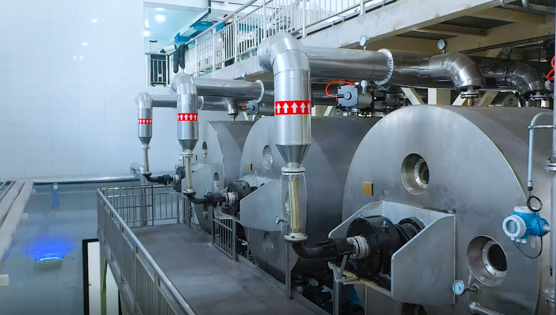
Shell and Tube Exchange heat exchangers are widely used in various industries for transferring heat between two fluids. The basic design of a shell and tube heat exchanger consists of a shell with a bundle of tubes inside it. One fluid flows through the tubes while the other fluid flows around the tubes in the shell. The fluids are separated by a thin metal wall, which allows heat to transfer between them.

Shell and Tube Exchange heat exchangers are used in many applications, including power plants, chemical plants, and oil refineries. They are often used to cool or heat fluids, such as water, oil, or gases. The design of a shell and tube heat exchanger can vary depending on the application. Factors such as the flow rate, temperature, and pressure of the fluids, as well as the space available for the heat exchanger, must be considered when designing the heat exchanger.
Design Principles
Thermal Design
The thermal design of a Shell and Tube Exchange involves the determination of heat transfer area, number of tubes, tube size, tube layout, and the selection of baffle type. These parameters are influenced by several factors such as the nature of the fluids, temperature, pressure, flow rate, and fouling resistance.
The heat transfer area is calculated based on the heat duty and the overall heat transfer coefficient. The number of tubes is determined based on the flow rate and the velocity of the fluid in the tube. The tube size is selected based on the pressure drop and the allowable velocity in the tube.
The tube layout and the baffle type are chosen based on the nature of the fluids and the desired heat transfer characteristics. The tube layout can be in-line or staggered, and the baffle type can be segmental, helical, or rod-baffle.
Mechanical Design
The mechanical design of a shell and tube heat exchanger involves the determination of the shell thickness, tube thickness, and the selection of materials. These parameters are influenced by several factors such as the pressure, temperature, and the nature of the fluids.
The shell thickness is calculated based on the pressure and the allowable stress of the material. The tube thickness is determined based on the pressure and the allowable stress of the material, and the tube diameter.
The materials of construction are selected based on the nature of the fluids and the operating conditions. Common materials of construction include carbon steel, stainless steel, and copper alloys.
Overall, the design principles of a shell and tube heat exchanger are critical to ensure efficient and reliable heat transfer. The thermal and mechanical design parameters must be carefully considered to achieve optimal performance.
Components of Shell and Tube Heat Exchangers
Shell and tube heat exchangers are widely used in various industries for heat transfer applications. These heat exchangers are composed of several components that work together to transfer heat from one fluid to another. The following are the main components of shell and tube heat exchangers:
Tubes
Tubes are the primary components of shell and tube heat exchangers. They are responsible for transferring heat between the two fluids. Tubes are usually made of materials such as copper, steel, or titanium, depending on the application. The size and number of tubes in a heat exchanger depend on the heat transfer requirements.
Shells
Shells are the outermost component of shell and tube heat exchangers. They enclose the tubes and provide a pathway for the fluid to flow through the tubes. Shells are usually made of materials such as carbon steel, stainless steel, or titanium, depending on the application.
Tube Sheets
Tube sheets are the components that hold the tubes in place within the heat exchanger. They are usually made of the same material as the shell. Tube sheets are designed to withstand the pressure and temperature of the fluids flowing through the tubes.
Baffles
Baffles are the components that are placed inside the shell to direct the flow of fluids. They are usually made of the same material as the shell. Baffles help to increase the heat transfer efficiency by creating turbulence in the fluid flow.
Tie Rods and Spacers
Tie rods and spacers are the components that hold the shell and tube assembly together. They are usually made of materials such as carbon steel or stainless steel. Tie rods and spacers help to maintain the proper spacing between the tubes and prevent them from vibrating or sagging.
In summary, shell and tube heat exchangers are composed of several components that work together to transfer heat from one fluid to another. Tubes, shells, tube sheets, baffles, tie rods, and spacers are the main components of these heat exchangers. The selection of materials and the design of these components depend on the specific application requirements.
Classification
Shell and tube heat exchangers are classified based on their design and construction. The three main types of shell and tube heat exchangers are fixed tube sheet, U-tube design, and floating head.
Fixed Tube Sheet
Fixed tube sheet heat exchangers are the simplest and most common type of shell and tube heat exchanger. In this design, the tubes are fixed to a tube sheet that is welded to the shell. The tube sheet does not move, and the tubes expand and contract freely with temperature changes. Fixed tube sheet heat exchangers are suitable for low to moderate temperature and pressure applications.
U-Tube Design
U-tube heat exchangers are used when thermal expansion is a concern. In this design, the tubes are bent into a U-shape, and the ends are fixed to a tube sheet that is welded to the shell. The U-tube design allows the tubes to expand and contract freely without putting stress on the shell or tube sheet. U-tube heat exchangers are suitable for high temperature and pressure applications.
Floating Head
Floating head heat exchangers are used when frequent cleaning or maintenance is required. In this design, one end of the shell is fixed, and the other end is free to move. The tube sheet is attached to the fixed end, while the floating head is attached to the other end. The floating head can be easily removed for cleaning or maintenance. Floating head heat exchangers are suitable for high-temperature applications and corrosive fluids.
In summary, shell and tube heat exchangers are classified based on their design and construction. Fixed tube sheet, U-tube design, and floating head are the three main types of shell and tube heat exchangers. Each design has its advantages and limitations, and the selection should be based on the specific application requirements.
Material Selection
When selecting materials for shell and tube heat exchangers, several factors need to be considered. These include corrosion resistance, thermal conductivity, and mechanical strength.
Corrosion Resistance
Corrosion is a major concern in shell and tube heat exchangers, as it can lead to reduced efficiency and even failure. Materials with good corrosion resistance, such as stainless steel, titanium, and nickel alloys, are commonly used in the construction of heat exchangers.
Thermal Conductivity
Thermal conductivity is another important factor to consider when selecting materials for heat exchangers. Materials with high thermal conductivity, such as copper and aluminum, are ideal for use in the tubes of heat exchangers. These materials allow for efficient heat transfer and can help to improve the overall performance of the heat exchanger.
Mechanical Strength
In addition to corrosion resistance and thermal conductivity, mechanical strength is also an important consideration when selecting materials for heat exchangers. Materials with high mechanical strength, such as carbon steel and titanium, are commonly used in the construction of heat exchangers. These materials are able to withstand the high pressures and temperatures that are often encountered in heat exchanger applications.
Overall, the selection of materials for shell and tube heat exchangers is a critical factor in ensuring their performance and longevity. By carefully considering factors such as corrosion resistance, thermal conductivity, and mechanical strength, engineers can select materials that are best suited for their specific application.
Heat Transfer Theory
Overall Heat Transfer Coefficient
The overall heat transfer coefficient (U) is a measure of the rate of heat transfer across a surface. It is a combination of the conductive and convective heat transfer coefficients and takes into account the thermal resistances of both the shell and tube sides of the exchanger. The overall heat transfer coefficient is important in determining the heat transfer rate and the size of the heat exchanger required.
Log Mean Temperature Difference
The log mean temperature difference (LMTD) is a measure of the temperature difference between the hot and cold fluids in a heat exchanger. It takes into account the fact that the temperature difference between the two fluids changes as they flow through the exchanger. The LMTD is used in the calculation of the heat transfer rate and is an important parameter in the design of the heat exchanger.
Heat Exchanger Effectiveness
The heat exchanger effectiveness (ε) is a measure of the efficiency of the heat exchanger. It is defined as the ratio of the actual heat transfer rate to the maximum possible heat transfer rate. The effectiveness of the heat exchanger depends on the design of the exchanger and the properties of the fluids being used. A higher effectiveness indicates a more efficient heat exchanger.
In summary, the heat transfer theory is an important aspect of the design and operation of shell and tube heat exchangers. The overall heat transfer coefficient, log mean temperature difference, and heat exchanger effectiveness are key parameters that must be considered in order to achieve efficient and effective heat transfer.
Flow Arrangements
Shell and Tube Exchange can be designed with different flow arrangements based on the direction of the fluid flow. The three most common flow arrangements are parallel flow, counter flow, and cross flow.
Parallel Flow
In parallel flow, both the hot and cold fluids enter the heat exchanger at the same end and flow parallel to each other. This arrangement is simple and efficient but has a limited heat transfer capacity. Parallel flow is commonly used in applications where small temperature differences between the hot and cold fluids are required.
Counter Flow
In counter flow, the hot and cold fluids enter the heat exchanger at opposite ends and flow in opposite directions. This arrangement provides a higher heat transfer capacity than parallel flow and is commonly used in applications where large temperature differences between the hot and cold fluids are required.
Cross Flow
In cross flow, the hot and cold fluids flow perpendicular to each other. This arrangement is not as efficient as parallel or counter flow, but it is useful in applications where space is limited. Cross flow heat exchangers are commonly used in HVAC systems and air conditioning units.
Each flow arrangement has its own advantages and disadvantages, and the choice of flow arrangement depends on the specific requirements of the application. Proper selection of the flow arrangement can optimize heat transfer efficiency and reduce energy consumption.
Operational Considerations
Pressure Drop
One of the key operational considerations for shell and tube heat exchangers is pressure drop. As the fluid flows through the heat exchanger, it encounters resistance from the tube bundle and the shell side baffles. This resistance results in a pressure drop across the heat exchanger, which can have a significant impact on the overall system performance.
To minimize pressure drop, it is important to design the heat exchanger with an appropriate number of tubes and baffles. Increasing the number of tubes and baffles can help to reduce the velocity of the fluid, which in turn reduces the pressure drop. However, it is important to balance this with the need to maintain a high heat transfer rate.
Temperature Control
Another important consideration for shell and tube heat exchangers is temperature control. In some applications, it is critical to maintain a specific temperature range in order to ensure product quality or process efficiency.
To achieve accurate temperature control, it is important to design the heat exchanger with an appropriate number of tubes and baffles, as well as the correct fluid flow rates. Additionally, temperature sensors should be installed at key points in the system to monitor the temperature and provide feedback to the control system.
Vibration and Noise
Vibration and noise can also be a concern in shell and tube heat exchangers, particularly in high-pressure or high-velocity applications. Excessive vibration can lead to mechanical failure or damage to the heat exchanger, while noise can be a nuisance for operators and nearby workers.
To minimize vibration and noise, it is important to design the heat exchanger with appropriate supports and damping systems. Additionally, it may be necessary to use noise-reducing materials or enclosures to minimize the impact of noise on the surrounding environment.
Maintenance and Cleaning
Chemical Cleaning
To maintain the efficiency of a shell and tube heat exchanger, chemical cleaning is recommended. Chemical cleaning is a process that involves the use of chemicals to remove deposits and contaminants that have accumulated on the heat transfer surfaces. This process is effective for removing scale, rust, and other types of deposits that can reduce the heat transfer rate of the exchanger.
The chemical cleaning process involves circulating a cleaning solution through the exchanger. The solution is typically composed of acid or alkaline-based chemicals that can dissolve the deposits. The cleaning solution is then flushed out of the exchanger with water.
Mechanical Cleaning
Mechanical cleaning is another method of cleaning a shell and tube heat exchanger. This process involves physically removing the deposits from the heat transfer surfaces. Mechanical cleaning is typically used when the deposits are too hard or stubborn to be removed by chemical cleaning.
Mechanical cleaning can be done using a variety of methods, including brushing, scraping, and high-pressure water jetting. The method used will depend on the type and severity of the deposits.
Inspection and Testing
Regular inspection and testing of a shell and tube heat exchanger is essential to ensure its continued performance and longevity. Inspections should be carried out at least once a year and should include a visual inspection of the exchanger’s internal and external surfaces.
Testing should also be carried out to check the exchanger’s performance. This can be done by measuring the temperature and pressure drop across the exchanger. Any significant changes in these measurements can indicate a problem with the exchanger.
In conclusion, regular maintenance and cleaning of a shell and tube heat exchanger is essential to ensure its continued performance and longevity. Chemical and mechanical cleaning are effective methods of removing deposits, and regular inspection and testing can help identify any potential problems early on.
Applications and Industries
Petrochemical Industry
Shell and tube heat exchangers are widely used in the petrochemical industry due to their ability to handle high pressure and temperature conditions. They are used for a variety of applications such as cooling and condensing of gases, heating and cooling of liquids, and heat recovery.
In the petrochemical industry, shell and tube heat exchangers are used in processes such as distillation, cracking, and reforming. They are also used in the production of various chemicals such as ethylene, propylene, and butadiene.
Power Generation
Shell and tube heat exchangers are also used in power generation plants for various applications such as cooling of turbine oil, cooling of generator stator water, and condensing of steam.
In power generation plants, shell and tube heat exchangers are used in processes such as steam generation, steam turbine cycle, and cooling water systems. They are also used in combined cycle power plants to recover waste heat from gas turbines.
Food and Beverage
Shell and Tube Exchange are used in the food and beverage industry for various applications such as pasteurization, sterilization, and cooling.
In the food and beverage industry, shell and tube heat exchangers are used in processes such as milk processing, beer brewing, and juice production. They are also used in the production of various food products such as soups, sauces, and jams.
Overall, Shell and Tube Exchange are versatile and widely used in various industries due to their ability to handle high pressure and temperature conditions, and their efficiency in heat transfer.
Standards and Certifications
When it comes to Shell and Tube Exchange, there are several standards and certifications that manufacturers must adhere to in order to ensure safety, reliability, and quality of their products. Here are some of the most important ones:
ASME
The American Society of Mechanical Engineers (ASME) Boiler and Pressure Vessel Code is widely recognized as the leading standard for pressure equipment design and fabrication. ASME Section VIII, Division 1, provides rules for the design, fabrication, testing, and certification of pressure vessels, including shell and tube heat exchangers. Manufacturers who want to certify their products to ASME standards must follow strict guidelines and undergo rigorous inspections by authorized third-party organizations.
TEMA
The Shell and Tube Exchange Manufacturers Association (TEMA) is a trade association of companies that design and fabricate shell and tube heat exchangers. TEMA has developed a set of standards and guidelines for the design, construction, and testing of heat exchangers, including the classification of exchangers into three types: A, B, and C. Type A exchangers are the most common and have a removable bundle, while Type B and C exchangers have fixed tubesheets.
API
The American Petroleum Institute (API) is a trade association that represents the oil and gas industry in the United States. API has developed several standards and recommended practices for the design, construction, and operation of heat exchangers used in the industry. API 660 is the most widely used standard for shell and tube heat exchangers in the petroleum industry, and provides guidelines for the design, materials, fabrication, inspection, and testing of exchangers.
In conclusion, Shell and Tube Exchange adhering to these standards and certifications is crucial for ensuring the safety, reliability, and quality of shell and tube heat exchangers. Manufacturers who follow these guidelines can provide their customers with products that meet the highest standards of performance and durability.