Shell and Tube Condensers: A Comprehensive Guide to their Design and Applications
Shell and Tube Condensers: A Comprehensive Guide to their Design and Applications
Shell and tube condensers are a type of heat exchanger commonly used in industrial and commercial applications. They are designed to transfer heat from a hot fluid, typically a vapor, to a cooler fluid, usually a liquid, by passing the hot fluid through a series of tubes that are surrounded by the cooler fluid. The tubes are typically made of materials such as copper, stainless steel, or titanium, while the shell is made of materials such as carbon steel or stainless steel.
One of the key advantages of shell and tube condensers is their efficiency in transferring heat. The design allows for a large surface area for heat transfer, which means that more heat can be transferred in a shorter amount of time. Additionally, the use of multiple tubes allows for a greater volume of fluid to be processed, further increasing efficiency. Shell and tube condensers are also known for their durability and reliability, making them a popular choice for demanding applications.
Basic Principles of Condensation

Phase Change Fundamentals
Condensation is the process of transforming a vapor into a liquid by removing heat. This phase change occurs when the vapor reaches a temperature lower than its saturation point, which is the temperature at which the vapor will start to condense. The saturation point depends on the pressure of the vapor and the properties of the fluid.
When a vapor condenses, it releases latent heat, which is the heat required to change the phase of the fluid. This heat is transferred to the cooling medium, which can be a liquid or a gas. The cooling medium removes the heat from the condenser and carries it away, allowing the vapor to condense into a liquid.
Heat Transfer Mechanisms
The heat transfer mechanisms in a shell and tube condenser involve convection and conduction. Convection is the transfer of heat from the vapor to the cooling medium through the movement of the fluid. Conduction is the transfer of heat through a solid material, such as the tube walls of the condenser.
The design of the condenser determines the efficiency of the heat transfer mechanisms. The surface area of the tubes, the flow rate of the cooling medium, and the temperature difference between the vapor and the cooling medium all affect the rate of heat transfer.
Overall, understanding the basic principles of condensation is essential for designing and operating efficient shell and tube condensers.
Design and Construction of Shell and Tube Condensers

Main Components
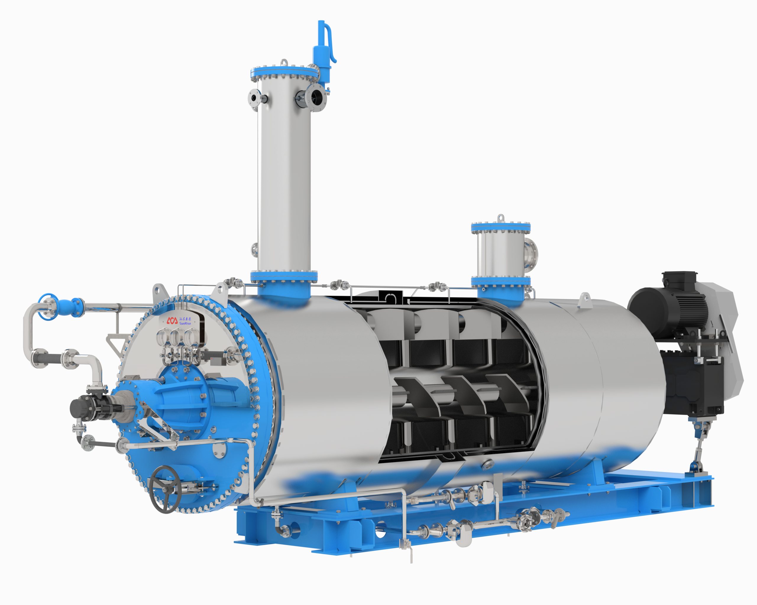
Shell and tube condensers are widely used in industrial applications to condense vapor into a liquid. The main components of a shell and tube condenser include a shell, tubes, tube sheets, baffles, and a bundle support plate. The shell is a cylindrical vessel that contains the tubes and serves as a housing for the condenser. The tubes are typically made of copper, brass, or stainless steel and are arranged in a bundle within the shell. The tube sheets are located at each end of the shell and serve to support and seal the tubes. Baffles are used to direct the flow of the fluid and increase heat transfer efficiency. The bundle support plate is located at the bottom of the shell and supports the weight of the tube bundle.
Materials of Construction
The materials of construction for shell and tube condensers depend on the application and the fluids being handled. The shell and tube sheets are usually made of carbon steel, stainless steel, or a combination of both. The tubes are typically made of copper, brass, or stainless steel. The choice of materials depends on factors such as the corrosiveness of the fluids, the operating temperature and pressure, and the cost of the materials.
Tubular Heat Exchanger Standards
Tubular heat exchangers, including shell and tube condensers, are designed and constructed according to various industry standards such as ASME, TEMA, and API. These standards provide guidelines for the design, fabrication, and testing of shell and tube condensers to ensure their safety and reliability. The standards also specify the requirements for materials of construction, welding, and inspection.
In conclusion, shell and tube condensers are an essential component in many industrial processes. Their design and construction are critical to their performance and reliability. By following industry standards and selecting appropriate materials of construction, shell and tube condensers can operate efficiently and safely for many years.
Types of Shell and Tube Condensers

Shell and tube condensers are widely used in various industries for heat transfer purposes. These condensers are efficient and reliable, and they come in different types based on their design and application. In this section, we will discuss some of the common types of shell and tube condensers.
Horizontal vs. Vertical Orientation
Shell and tube condensers can be designed with either a horizontal or vertical orientation. The choice of orientation depends on the available space, the type of fluid being used, and the flow rate. Horizontal condensers are typically used for low to medium flow rates, while vertical condensers are used for high flow rates. Vertical condensers are also preferred when space is limited.
Fixed Tube Sheet
In a fixed tube sheet condenser, the tubes are fixed to the tube sheet, which is then welded to the shell. This type of condenser is simple and cost-effective, but it has limited flexibility. The tube sheet can only expand or contract within certain limits, which can cause thermal stresses and reduce the lifespan of the condenser.
U-tube Design
In a U-tube condenser, the tubes are bent in a U-shape and fixed to the tube sheet. This design allows for thermal expansion and contraction, which reduces stress on the tube sheet and increases the lifespan of the condenser. U-tube condensers are commonly used in applications where thermal cycling is frequent.
Floating Head Type
In a floating head condenser, the tube sheet is not fixed to the shell, and the tube bundle can move freely within the shell. This design allows for easy maintenance and cleaning, but it is more expensive than fixed tube sheet condensers. Floating head condensers are commonly used in applications where frequent cleaning is required.
In conclusion, shell and tube condensers come in different types, each with its own advantages and disadvantages. The choice of condenser depends on the specific application and requirements. By understanding the different types of shell and tube condensers, engineers can make informed decisions and select the best condenser for their needs.
Thermal and Hydraulic Design
Condenser Heat Duty Calculation
The heat duty of a shell and tube condenser is calculated based on the mass flow rate of the process fluid and the temperature difference between the inlet and outlet of the fluid. The heat transfer coefficient, which is dependent on the physical properties of the fluids, is also taken into consideration. The heat duty can be calculated using the following equation:
Q = m * Cp * ΔT
where Q is the heat duty, m is the mass flow rate of the process fluid, Cp is the specific heat capacity of the fluid, and ΔT is the temperature difference between the inlet and outlet of the fluid.
Pressure Drop Considerations
The pressure drop across a shell and tube condenser is an important factor to consider in the design process. The pressure drop is caused by the frictional resistance of the fluid as it flows through the tubes and the shell. The pressure drop can be calculated using the following equation:
ΔP = f * (L/D) * (ρ/2) * (V^2)
where ΔP is the pressure drop, f is the friction factor, L is the length of the tube, D is the diameter of the tube, ρ is the density of the fluid, and V is the velocity of the fluid.
Cooling Water Flow Design
The cooling water flow rate is an important parameter in the design of a shell and tube condenser. The cooling water flow rate is dependent on the heat duty of the process fluid and the temperature difference between the inlet and outlet of the cooling water. The cooling water flow rate can be calculated using the following equation:
m = Q / (Cp * ΔT)
where m is the mass flow rate of the cooling water, Cp is the specific heat capacity of the cooling water, and ΔT is the temperature difference between the inlet and outlet of the cooling water.
In order to ensure proper cooling of the process fluid, the cooling water flow rate should be sufficient to remove the heat generated by the process fluid.
Operational Considerations
Condensate Subcooling
Condensate subcooling is a critical factor in the operation of shell and tube condensers. It is the process of cooling the condensate below its saturation temperature to prevent flashing or vaporization. This is achieved by providing a subcooling zone in the condenser. The subcooling zone is usually located at the bottom of the condenser where the coldest cooling medium is present.
The benefits of condensate subcooling include reducing the load on downstream equipment, improving the efficiency of the overall system, and reducing the risk of water hammer. It is important to note that too much subcooling can lead to excessive pressure drop, reduced heat transfer, and increased fouling.
Non-condensable Gases Handling
Non-condensable gases are gases that do not condense at the operating temperature and pressure of the condenser. They can accumulate in the condenser and reduce its efficiency by forming a barrier to heat transfer. Therefore, it is important to remove them from the system.
One way to handle non-condensable gases is by providing a vent at the top of the condenser. The vent allows the gases to escape, ensuring that the condenser operates at its maximum efficiency. Another way is to use a vacuum pump to remove the gases from the system.
It is important to note that the presence of non-condensable gases can be an indication of leaks in the system. Therefore, it is important to identify and repair any leaks as soon as possible to prevent further damage to the system.
Maintenance and Cleaning
Routine Maintenance Practices
To maintain the efficiency and longevity of shell and tube condensers, regular maintenance practices should be followed. These practices include inspecting the condenser for leaks, checking the water flow rate, and monitoring the temperature and pressure of the refrigerant and water.
It is recommended to inspect the condenser at least once a year, preferably before the start of the cooling season. During the inspection, the technician should check for any signs of corrosion, fouling, or damage to the tubes and the shell. Any leaks should be repaired immediately to prevent further damage.
Checking the water flow rate is also crucial for the proper functioning of the condenser. A low flow rate can lead to reduced heat transfer and increased energy consumption. The technician should ensure that the water flow rate is within the manufacturer’s recommended range.
Monitoring the temperature and pressure of the refrigerant and water is another important maintenance practice. Any significant deviations from the recommended values should be investigated and corrected promptly.
Cleaning Techniques
Over time, shell and tube condensers can become fouled with deposits of scale, dirt, and other impurities. This fouling can reduce the heat transfer efficiency of the condenser and increase energy consumption. Therefore, regular cleaning of the condenser is necessary to maintain its performance.
The cleaning technique used depends on the type and extent of fouling. For light fouling, a water flush or a mild detergent solution can be used to clean the tubes. For heavier fouling, chemical cleaning may be required.
Chemical cleaning involves the use of acidic or alkaline solutions to dissolve the deposits. The technician should follow the manufacturer’s instructions for the cleaning solution and ensure that the solution is flushed out thoroughly after cleaning.
In addition to cleaning the tubes, the shell of the condenser should also be cleaned periodically. The shell can be cleaned using a high-pressure water jet or a mild detergent solution. The technician should ensure that the cleaning solution is compatible with the materials of construction of the condenser.
Overall, regular maintenance and cleaning of shell and tube condensers are essential for their efficient and reliable operation. By following these practices, the condenser can provide optimal performance and a longer service life.
Categories
Recent Posts
-

Fishmeal Prices Surge: Custom Equipment Delivers Greater Value for Feed Producers
July 20, 2026 -
Intelligent Batch Cooker: A New Benchmark for High Efficiency and Energy Saving
July 10, 2026 -
The Chemistry of Rendering Odors: Why High-Temperature Processing Creates Them and the Engineering Controls That Work
July 6, 2026